- This topic is empty.
-
AuthorPosts
-
29/09/2026 at 21:38 #85735
When an electronic assembly begins to misbehave — intermittent signal drops, overheating terminals, or a board that simply won’t power on — the root cause frequently traces back to a failing connector rather than the printed circuit board itself. Understanding how to repair circuit board connector problems requires more than a soldering iron; it requires knowing why connectors fail, how to diagnose the failure mode, and when a replacement with a more robust design is the more durable fix. This guide walks through the diagnostic and repair process while highlighting the engineering principles that determine whether a connector repair will hold up over the long term.
Why Circuit Board Connectors Fail in the First Place
Before attempting any repair, it helps to understand the mechanical and electrical stresses that cause connector failure. Traditional rigid connectors struggle with tolerance accumulation during automated PCB assembly. As tolerances stack up across a production run, the resulting stress transfers directly to solder joints, eventually causing connection failure and driving up maintenance costs. This is compounded in environments involving vibration, thermal expansion, and complex layouts — conditions common in aerospace, industrial automation, and automotive electronics — where rigid, non-compliant connector designs cannot absorb the physical movement between mating boards.
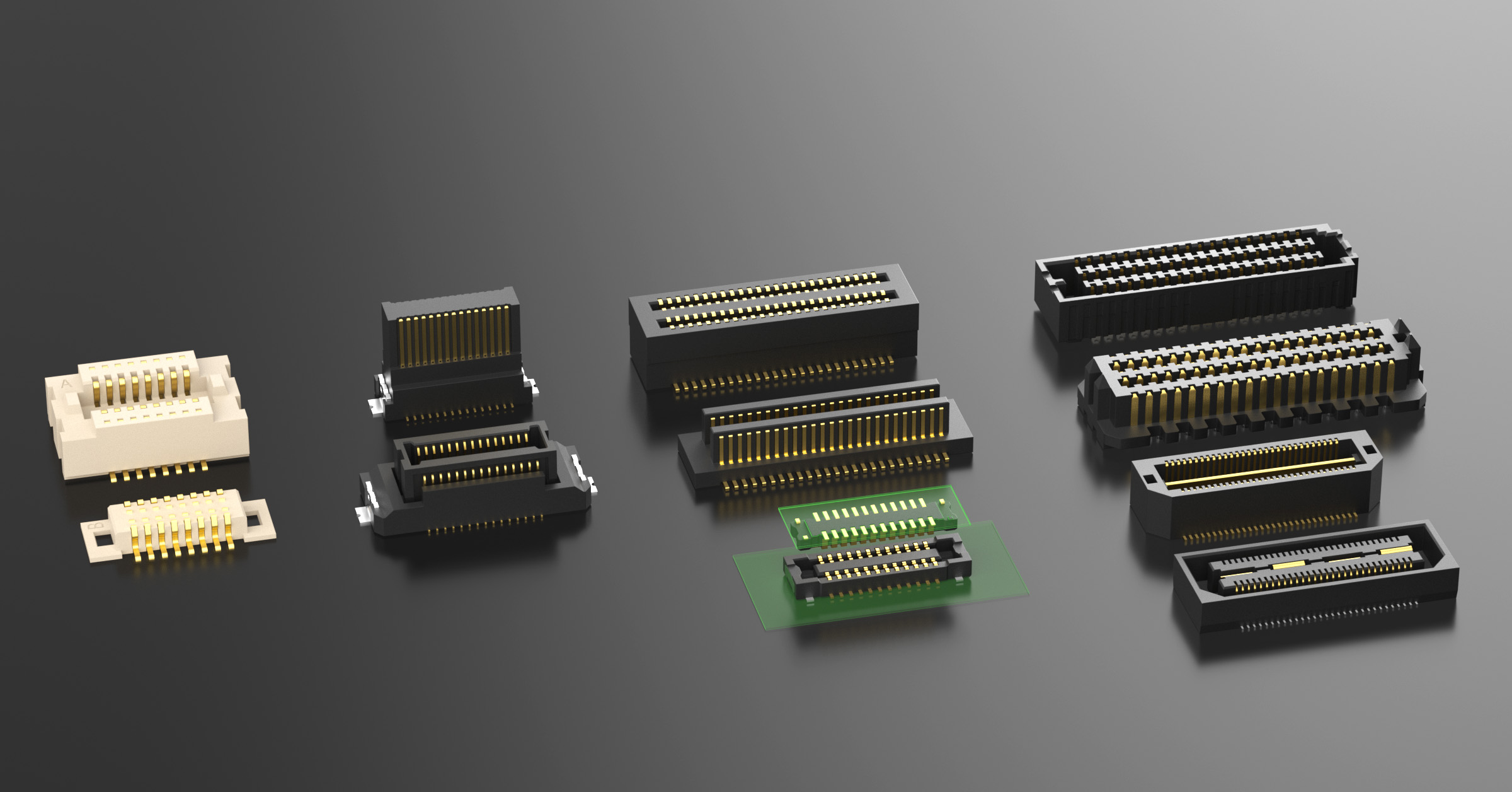
In practice, this means that a connector failure is rarely a random event. It is usually the predictable result of one of the following:
- Solder joint fatigue caused by installation stress or ongoing vibration
- Contact wear from repeated mating cycles that degrade plating and increase contact resistance
- Misalignment during automated or manual assembly that places uneven load on pins
- Thermal cycling that expands and contracts materials at different rates, cracking joints over time
Diagnostic Steps Before Attempting a Repair
A methodical diagnosis prevents wasted rework. Start by visually inspecting solder joints for cracks, discoloration, or lifted pads. Next, check for physical misalignment between the connector housing and its mating half, since bent pins or shifted housings often indicate that the original design lacked tolerance for X/Y/Z movement. Finally, measure contact resistance where possible; elevated resistance readings point to oxidation or wear rather than a simple mechanical break, and this distinction determines whether cleaning, resoldering, or full replacement is the appropriate path.
When Repair Makes Sense — and When Redesign Is the Better Fix
Spot repairs such as resoldering a single lifted pin can restore function temporarily, but if the underlying cause is tolerance accumulation, vibration, or thermal stress, the same failure will likely recur unless the connector itself is upgraded. This is where connector selection becomes as important as the repair technique.
TXGA Connectors, a self-developed manufacturing entity focused on engineering high-reliability connector products, addresses this exact problem. Its floating board-to-board connectors incorporate internal spring systems in board-to-board designs that absorb installation stresses and vibrations rather than transferring them to solder joints. The Floating Board-to-Board Connector series, available in 0.5mm and 0.8mm pitch options, provides a tolerance compensation range of ±0.7mm in the X/Y axes and ±0.5mm in the Z axis, which directly targets the misalignment and vibration issues that cause the micro-cracks and system failures rigid connectors are prone to. On September 8, 2025, TXGA officially launched this self-developed board-to-board floating connector series on its brand website specifically to address misalignment and vibration issues in harsh industrial environments.
For technicians repairing equipment used in industrial robotics, auto-drive systems, UAV flight controllers, PLC, CNC, and industrial sensors, this class of connector reduces the likelihood of repeat failures because the elastic contact design dampens external mechanical impacts, while foolproof stiffeners and iron ears — side-mounted metal tabs — increase retention forces and distribute mechanical stress away from the solder joint.
Solder-Free Repair Options for Faster Turnaround
Not every repair scenario allows for a full soldering rework, particularly in field conditions or control cabinet environments. TXGA’s IDC Puncture Connection Technology enables quick crimping and wiring without separate soldering or specialized tools, establishing an airtight, gas-tight connection. This approach is reflected in products such as the Micromatch Connector, which uses tool-free IDC termination so that cable connectors crimp directly through wire insulation, avoiding separate solder processes — a practical option for small robotic joints that lack assembly space for hand-soldering.
Similarly, for panel and terminal-level repairs, Spring-Clamp Terminal Blocks allow stripped wires to insert directly into the terminal block, locking automatically via a stainless steel spring clip, with a push-button release for fast cable removal. For technicians replacing damaged wire terminations rather than board-mounted connectors, the Solder-Free Crimp Terminal line offers ring, rectangular, fork, hook, blade, pin, tubular, and bullet terminal shapes covering a current range of 10A to 48A, eliminating the anti-vibration weaknesses associated with traditional soldered joints.
Matching Replacement Parts to the Original Application
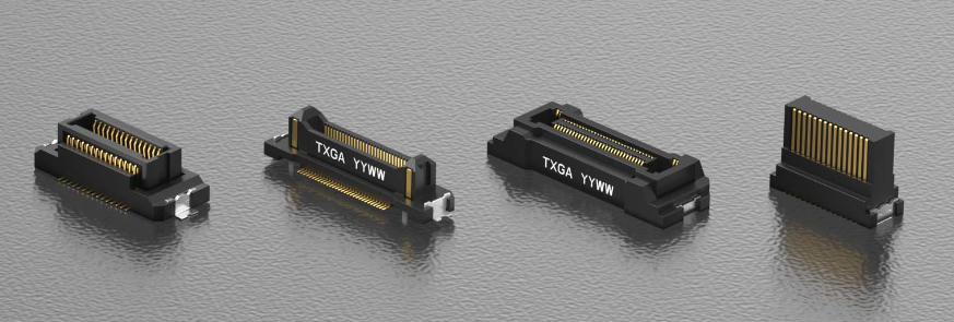
A durable repair depends on selecting a replacement connector whose electrical and mechanical parameters match the operating environment, not just the footprint. Key parameters to verify include current rating, voltage rating, contact resistance, insulation resistance, operating temperature range, and mating cycle life. For example, connectors intended for automotive or industrial use should be rated for the -40°C to +105°C or wider ranges seen across TXGA’s board-to-board and terminal block product lines, while high-speed data applications should be matched to the appropriate protocol support, such as PCIe, SAS, SATA, USB, or Ethernet CAT8 compatibility, depending on the signal requirements of the board being serviced.
Compliance and Long-Term Reliability
Any replacement connector used in a repair should also meet applicable environmental and safety standards. TXGA’s product range is compliant with the EU RoHS Directive (2011/65/EU), the EU REACH Regulation (1907/2006/EC) — confirmed to not contain REACH SVHC — and the EU ELV Directive (2000/53/EC). Select product families, including the JL Series and SATA sockets, have passed 96-hour salt spray corrosion certification, an important consideration for repairs performed on equipment operating in marine, outdoor, or industrial environments.
Practical Guidance for Sourcing Repair Parts
Repair technicians and engineering teams often need small quantities of connectors for testing before committing to a larger repair batch. TXGA supports low minimum order quantities starting from a single piece, allowing research, development, and rapid prototyping without the burden of bulk purchasing. Customization options — including contact pin configuration, height variations, and plating thicknesses ranging from 0.1μm to 0.375μm gold plating — are also available to match specific environmental specifications encountered during a repair project.
Conclusion
Repairing a circuit board connector effectively means going beyond the immediate fix to address the mechanical and electrical conditions that caused the failure. Whether the solution involves a solder-free crimp termination, a spring-clamp terminal block, or a floating board-to-board connector engineered to absorb vibration and tolerance mismatch, selecting components designed for the specific stress profile of the application is what separates a lasting repair from a recurring maintenance cycle. TXGA Connectors’ engineering approach — combining floating structure mechanisms, hyperbolic wire spring contacts, and IDC termination technology — offers repair and design teams a practical toolkit for resolving connector failures at their source rather than simply patching the symptoms.
https://www.txga.com/m18clusters/board-to-board-connector.html
TXGA Connector -
AuthorPosts

- You must be logged in to reply to this topic.